
10 Energy-Saving Technologies for Tunnel Kiln Brick Plants
A practical engineering guide to VFDs, airflow control, heat recovery, insulation, combustion optimisation, high-temperature heat pumps and intelligent kiln automation.
For an ideal centrifugal fan, shaft power follows the cube of rotational speed.
Stabilise pressure, oxygen, moisture and production rate before sizing recovery equipment.
The best heat-recovery project starts after false air, excess air and surface losses are reduced.
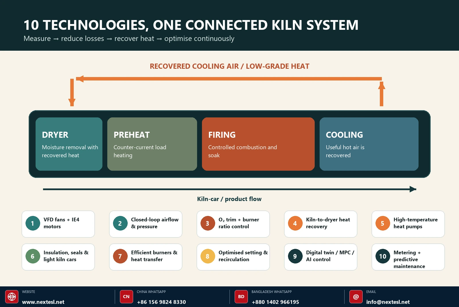
Tunnel kilns are already more continuous and heat-integrated than many batch kilns, yet a brick plant can still lose large amounts of purchased energy through unnecessary airflow, excess oxygen, hot exhaust, heavy kiln cars, poor sealing, unstable recipes and avoidable rejects. The strongest improvement programmes treat the kiln, dryer, fans, burners, product setting and controls as one thermal system—not as isolated machines.
This article explains ten technologies that can reduce specific energy consumption while protecting firing quality. It deliberately distinguishes established retrofits from emerging solutions. Actual results depend on clay chemistry, green-brick moisture, kiln geometry, product mix, throughput, fuel, ambient conditions and the condition of the existing plant.
Reduce purchased energy per saleable tonne while protecting kiln atmosphere, dryer stability, throughput and fired-brick quality. Every control change should be verified against those four constraints.
Combustion, pressure and fan changes must remain within the kiln supplier’s operating envelope and the plant’s burner-management, purge, flame-failure, gas-train and ventilation requirements. Never use an energy target to defeat a safety interlock or compromise required exhaust flow.
Start with a mass-and-energy baseline
A monthly fuel bill is not a kiln efficiency measurement. Production mix and inlet moisture can move energy use even when the kiln is operating identically. The minimum useful baseline pairs energy with saleable production and operating conditions.
Use lower heating value or higher heating value consistently, correct gas volume to the billing reference condition, and record both gross fired mass and saleable mass. The second denominator exposes energy lost through rejects. Segment results by brick format, body composition and firing curve.
| Variable | Recommended measurement | Minimum frequency | Why it matters |
|---|---|---|---|
| Fuel | Calibrated flow, pressure, temperature and heating value | 1 minute + daily total | Calculates thermal SEC and burner balance |
| Electricity | Submeters for exhaust, cooling, circulation and dryer fans | 1 minute + shift total | Separates fan savings from fuel savings |
| Production | Green, fired and saleable mass by product | Each kiln car / shift | Normalises energy and exposes reject energy |
| Moisture | Green-brick and dryer-exit moisture | Each product change; at least each shift | Quantifies the evaporation load |
| Atmosphere | O₂, CO where appropriate, pressure and temperature by critical zone | Continuous | Diagnoses excess air, false air and combustion risk |
| Heat streams | Flow and temperature for exhaust, cooling air and dryer supply/return | Continuous or campaign | Sizes heat-recovery opportunities |
| Quality | Colour, strength, dimensions, cracks and rejects | Lot / shift | Prevents false savings that damage saleable yield |
A useful heat balance assigns purchased energy to evaporation and reaction, sensible heat in product and kiln cars, stack loss, wall/roof loss, openings and leakage, and recoverable cooling heat. The U.S. Department of Energy’s process-heating guidance recommends a system approach that maps material and energy flows before individual projects are selected. See the DOE’s Process Heating Systems resources.
Technology comparison: where to look first
| # | Technology | Primary mechanism | Indicative energy impact to screen* | Maturity | Typical complexity |
|---|---|---|---|---|---|
| 1 | VFD fans + efficient motors | Matches fan speed to actual flow/pressure | 10–50% of affected fan electricity | Proven | Low–medium |
| 2 | Airflow and pressure control | Cuts false air, over-extraction and damper losses | 2–8% of kiln fuel; fan power also falls | Proven | Medium |
| 3 | O₂ trim + mass-ratio control | Maintains safe combustion with minimum excess air | 2–8% of kiln fuel where control is poor | Proven | Medium |
| 4 | Kiln-to-dryer heat recovery | Cascades cooling/exhaust heat to a useful sink | 5–20% of combined thermal demand at suitable sites | Proven | Medium–high |
| 5 | High-temperature heat pump | Upgrades low-grade heat for dryer duty | Site-specific fuel displacement; screen COP and temperature lift | Emerging | High |
| 6 | Insulation, seals, light kiln cars | Reduces surface, leakage and thermal-mass losses | 2–10% of kiln fuel on degraded/heavy systems | Proven | Low–high |
| 7 | Efficient burners and heat transfer | Improves mixing, turndown and convective transfer | 2–10% of kiln fuel, strongly baseline-dependent | Proven | Medium–high |
| 8 | Setting + recirculation optimisation | Improves gas–brick contact and temperature uniformity | 2–8% fuel or higher output at equal quality | Proven | Low–medium |
| 9 | Digital twin / MPC / AI | Optimises interacting set-points under changing load | Site/model-specific; lowers variability and overfiring | Advancing | High |
| 10 | Predictive energy management | Detects drift, degradation and avoidable idle loads | Typically a persistence enabler, not a one-off saving | Proven | Low–medium |
*Screening ranges prepared by NES Research Team from cited guidance, published studies and engineering practice. They refer to the affected energy stream, are not additive and are not guarantees. A calibrated site baseline is required.
VFD fans and high-efficiency motors
Replace throttling with speed control—but control a process variable, not just hertz.
Induced-draft, combustion-air, cooling-air, recirculation and dryer fans often spend long periods below their design duty while the motor continues near full speed and a damper wastes pressure. A variable-frequency drive (VFD) reduces fan speed so the fan produces only the required flow and pressure.
Under the ideal fan affinity laws, reducing speed to 80% requires about 51% of full-speed shaft power. Real systems deviate because of static pressure, leakage, drive losses and fan efficiency, but the principle remains powerful. The DOE describes the cube relationship and identifies centrifugal fans as prime adjustable-speed applications in its variable-speed fan case study.
Best candidates
- Fans controlled by throttling dampers or inlet vanes
- Large motors with variable recipes or throughput
- Fans that run during standby or production gaps
- Parallel fans where staging and speed control can be combined
Engineering checks
- Minimum safe purge and combustion airflow
- Motor cooling and torque at low speed
- VFD harmonics, cable length and bearing currents
- Fail-safe speed, bypass philosophy and damper position
Close the loop on kiln pressure, airflow, dryer humidity or temperature. A fixed reduced frequency can save electricity, but it will not respond safely to changing brick setting, filter resistance, weather or production rate. Trend fan speed, electrical power and the controlled process variable together.
Closed-loop airflow and kiln-pressure control
Stop heating air that the process does not need.
Excess extraction pulls cold air through car seals, doors, peepholes, joints and cracks. That false air must be heated, increases flue-gas volume, raises exhaust-fan demand and can disturb oxidation, cooling and temperature uniformity. Too little extraction, however, can cause hot-gas escape, unsafe conditions or product-quality problems.
The practical retrofit is a zone-based pressure and flow strategy: reliable pressure taps, purged impulse lines, differential transmitters, modulating dampers and VFD fans coordinated by the control system. The target is the minimum safe airflow that preserves the required atmosphere and pressure profile. There is no universal pressure set-point; it must be derived from kiln design, burner requirements, emissions control and product trials.
Commissioning sequence
- Repair false-air paths first. Smoke testing, door/seal inspection and pressure mapping prevent the controller from compensating for mechanical defects.
- Verify sensors under production conditions. Temperature, dust and condensate can bias pressure readings; use appropriate taps and maintenance access.
- Tune one loop at a time. Separate fast fan control from slower thermal and product responses to avoid oscillation.
- Prove the operating envelope. Test product changeovers, maximum and minimum throughput, power recovery and abnormal conditions.
Oxygen trim and digital air–fuel ratio control
Maintain complete, stable combustion without carrying unnecessary excess air.
Traditional linkages can drift as valves wear, gas pressure changes and burner zones modulate. Modern systems use measured fuel and combustion-air flow, cross-limited control, burner-zone pressure feedback and oxygen trim. The base ratio supplies a safe air–fuel relationship; the O₂ signal applies a slow correction for changing conditions.
Excess oxygen is not a simple “lower is better” variable. The correct operating window must account for burner design, fuel composition, clay reactions, carbon burnout, colour, carbon monoxide, emissions and temperature uniformity. Zirconia probes require the right location, leak-free sample paths where extractive systems are used, and routine calibration. A single stack O₂ value can also hide one fuel-rich zone and one air-rich zone.
Use cross-limiting so air leads fuel during firing-rate increases and fuel leads air during decreases. Keep flame supervision, purge logic and gas-pressure trips in an independent, validated burner-management layer.
The European Commission’s Ceramic Manufacturing BAT Reference Document lists automatic control, improved sealing, insulation, high-velocity burners and recovery of excess kiln heat among relevant efficiency techniques for ceramic manufacturing.
Waste-heat recovery from the cooling zone and exhaust
Match the cleanest, hottest source to the most stable nearby heat demand.
A tunnel kiln naturally produces valuable hot air as fired bricks cool. The first priority is usually direct reuse: route controlled cooling air to the dryer, pre-dryer or combustion-air system. Direct use avoids an extra energy conversion and often has better economics than generating electricity from modest-temperature heat.
Use a heat-cascade hierarchy
- Direct hot-air transfer to dryers where cleanliness and pressure balance permit.
- Combustion-air preheating with a recuperator where burner and NOx constraints are addressed.
- Indirect air-to-air or air-to-water exchange when streams must remain separated.
- Heat pump upgrading for low-grade heat that is too cool for direct dryer duty.
- Power generation only after stable thermal uses are exhausted and temperature/scale justify it.
Heat recovery needs more than a heat exchanger. Measure source and sink profiles over product cycles; allow for dust, condensation, corrosion and cleaning; include bypasses; and prevent dryer disturbances from propagating into the cooling zone. A published optimisation of recovered cooling air in a hollow-brick tunnel kiln reported about 4.6% natural-gas reduction at the calculated optimum, illustrating why “more recovery air” is not automatically better. See the Applied Thermal Engineering study.
The EU-funded DREAM ceramic-kiln project also investigated heat pipes, upgraded refractories and advanced control as an integrated furnace architecture—an instructive model for retrofit design.
High-temperature heat pumps for brick drying
Upgrade low-grade waste heat instead of discarding it.
After direct recovery is maximised, a high-temperature industrial heat pump can raise low-grade kiln or dryer exhaust heat to a useful dryer supply temperature. The application is usually the dryer—not the 900–1,100°C firing zone. Heat-pump performance is governed by source temperature, delivery temperature, humidity, fouling, refrigerant choice and the temperature lift.
The IEA reports that industrial heat pumps below 120°C have entered commercial operation and systems below 160°C are beginning to enter commercial service, while higher-temperature classes remain at demonstration, prototype or concept stage. See the IEA’s Heat Pump Monitor 2026.
Good fit
- Continuous low-grade heat source
- Stable dryer demand at achievable temperature
- High avoided-fuel cost or low-carbon electricity
- Short pipe runs and good condensate management
Poor fit
- Large source/sink timing mismatch
- Very high temperature lift
- Dust or corrosives without robust pretreatment
- Unreliable electricity or inadequate grid capacity
Screen the project with hourly source and sink curves, not annual averages. Include compressors, pumps, fans, defrost/cleaning where relevant and backup heat. Thermal storage can decouple the heat pump from short production disturbances and permit operation when electricity is cheaper or cleaner.
Advanced insulation, sealing and low-mass kiln cars
A persistent megawatt of surface loss is still a megawatt, even when it is difficult to see.
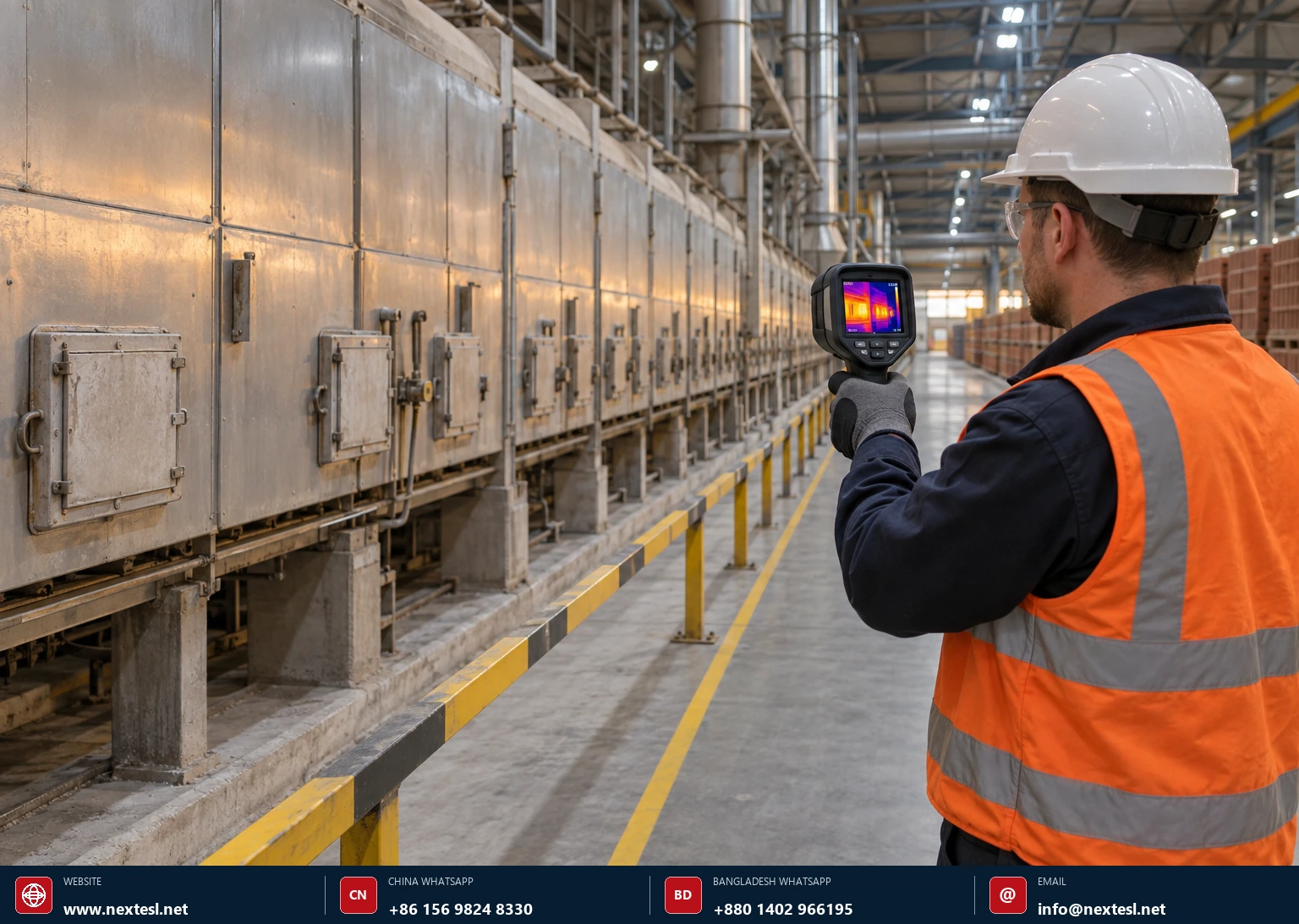
Radiation and convection from the kiln casing, roof, doors and car interface run continuously. Degraded refractory, compressed fibre modules, failed expansion joints and damaged car seals can also create local cold-air infiltration that forces higher firing input. The remedy starts with a thermal survey at stable load, supported by contact measurements and a defect register.
Retrofit options
- Repair door, sand, water, labyrinth or fibre seals according to the kiln design.
- Upgrade hot-face and backup insulation only after checking shell temperature, anchoring and chemical compatibility.
- Reduce kiln-car refractory mass with engineered lightweight systems where strength, thermal cycling and wheel loads permit.
- Improve car-to-car and car-to-wall sealing to prevent under-car heating and bypass flow.
- Add inspection ports and maintainable panel designs so performance persists after the shutdown.
Do not judge insulation solely by external temperature. A cooler shell may be beneficial, but refractory changes can shift internal temperature gradients, condensation points and structural expansion. Validate with the kiln designer and a controlled firing trial.
Efficient burners and intensified heat transfer
Deliver heat uniformly at useful turndown rather than compensating with peak temperature.
High-velocity burners can improve mixing and convective heat transfer, reducing temperature stratification. Modern modulating burners, electronic ratio control and appropriate staging can widen turndown and maintain stable flames across product changes. Recuperative or regenerative concepts may preheat combustion air, but their fit depends on flue-gas temperature, dust, emissions limits, burner arrangement and economics.
The goal is not the highest flame temperature. It is the required brick temperature history with the lowest safe fuel input and acceptable atmosphere. Excessive air preheat can alter flame speed, burner capacity and NOx; burner replacement therefore requires a combustion and emissions review.
Commission on product temperature, not gas temperature alone
Gas thermocouples respond faster than the brick core. Use instrumented kiln cars, sacrificial thermocouples, thermal-history devices or validated models to confirm the actual heatwork received by representative bricks in the setting.
Optimised brick setting and gas recirculation
The load pattern is part of the heat exchanger.
Brick spacing, orientation, pack density and channel alignment determine pressure drop and gas–solid heat transfer. An overly dense setting can create cold cores and long soak requirements; an overly open setting wastes kiln volume and can short-circuit flow. Computational fluid dynamics (CFD), pressure mapping and instrumented test cars can identify the best compromise for each product family.
Zone recirculation or pulsed/impinging flow may improve uniformity, particularly in preheating and cooling, allowing lower peak temperatures or faster travel without loss of quality. But added recirculation has an electrical cost. Optimise total energy and saleable throughput, not fuel alone.
Practical trial design
- Change one geometric variable at a time and mark each test car.
- Map temperature at edge, centre, top and bottom positions.
- Record pressure drop, fan power, firing curve and final quality.
- Hold green density and moisture within a controlled band.
- Compare energy per saleable tonne, not energy per car.
Digital twins, model-predictive control and AI
Coordinate slow thermal dynamics and interacting loops before deviations become defects.
A tunnel kiln has long delays: a control move made now may affect product quality hours later. Model-predictive control (MPC) estimates future zone and product behaviour, then adjusts burner demand, fan speed, pressure, recovery-air flow and car speed within defined constraints. A digital twin can combine first-principles heat balances with plant data; machine-learning “soft sensors” can estimate hard-to-measure states such as brick-core temperature or emerging quality risk.
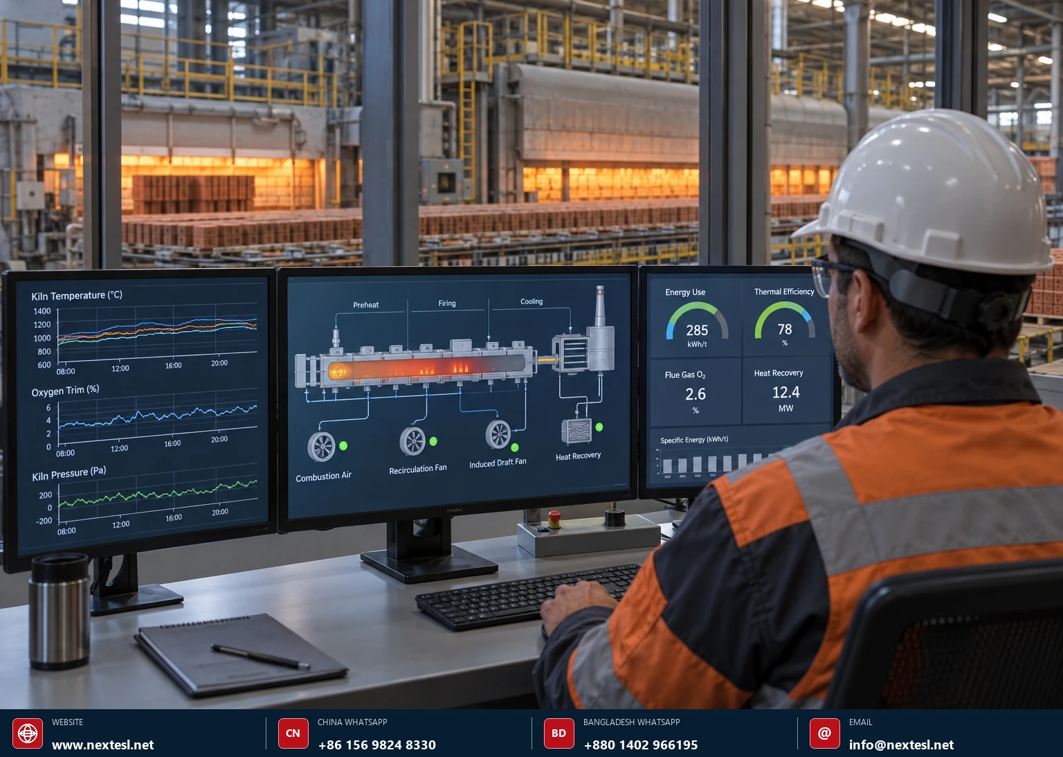
A 2024 peer-reviewed tunnel-kiln study developed a physics-based model that captures gas and solid temperatures, fuel use and product quality, then optimises set-points under changing production demand. The important lesson is architectural: the optimiser must respect product-quality and operating constraints, not chase energy alone. See Arvanitidis, Kostoglou and Georgiadis (2024).
Deploy in four confidence gates
- Historian and data-quality gate: calibrate timestamps, units, sensors and product genealogy.
- Shadow mode: compare model predictions with actual operation without controlling the kiln.
- Advisory mode: operators review recommended moves and reasons.
- Constrained closed loop: automate only within approved limits, with fallback and audit logs.
AI cannot correct a leaking kiln, biased O₂ probe or sticking damper. It can, however, find multivariable patterns and keep a well-maintained process closer to its best operating window. The IEA identifies process optimisation, energy management, motor efficiency, insulation and data-enabled AI as relevant industrial-efficiency measures in Energy Efficiency 2025.
Predictive maintenance and digital energy management
Make savings persist after commissioning.
Efficiency drifts. Damper linkages loosen, filters foul, pressure taps block, fan belts slip, bearings degrade, O₂ probes age and operators add conservative margin after a quality event. An energy-management layer detects the drift early by combining condition monitoring with normalised performance indicators.
Useful diagnostic signals
- Fan kW versus speed, flow and damper position
- O₂ by zone versus firing demand and pressure
- Shell thermal images at fixed operating points
- Motor current, vibration and bearing temperature
- Dryer exhaust humidity versus supply heat
Management indicators
- Thermal and electrical SEC by product
- Energy per saleable tonne and reject-energy cost
- Recovered heat used versus heat available
- Time outside approved recipe window
- Energy use during idle, hold and restart
Use alarms that describe an action, not just a number—for example, “exhaust fan power is 18% above the expected curve at this flow; inspect damper position, filter resistance and duct leakage.” Review the energy dashboard in the same daily meeting as throughput, quality, safety and maintenance.
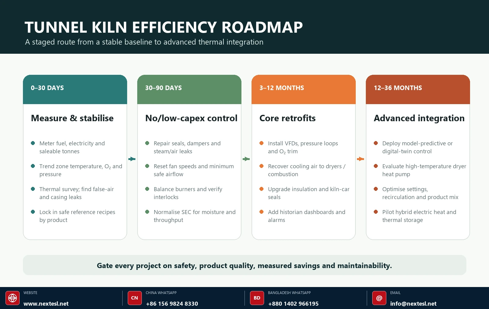
Implementation roadmap
Measure savings without double counting
Establish a representative baseline period, then adjust it for variables that materially influence energy use: saleable output, green-brick moisture, product type, firing temperature, ambient conditions and planned downtime. If VFDs and airflow controls are installed together, evaluate them as an interacting package unless submeters and test periods can separate their effects.
A strong measurement-and-verification plan defines meter boundaries, calculation intervals, adjustment variables, data exclusions, uncertainty and the party responsible for sign-off before the project begins.
Build the business case around net value
Annual net benefit should include avoided fuel and electricity, demand charges, reject reduction, increased saleable capacity and avoided maintenance—minus added electricity, consumables, cleaning, software, calibration and maintenance. Test the business case against energy-price, throughput and product-mix scenarios. For emerging systems, include integration risk and a staged performance test.
Innovation horizon: what comes after conventional efficiency?
Three developments are moving from research or early deployment toward industrial demonstration:
Hybrid electric firing
Resistance, induction or microwave energy can be combined with combustion to improve controllability or shift part of the heat load to electricity. Integration must address temperature uniformity, electrical capacity, refractory compatibility and total energy cost.
High-temperature thermal storage
Solid media—including ceramics—can store electrically generated heat and release it to process air, enabling load shifting and better use of variable renewable electricity.
Hydrogen-ready burners
Hydrogen can reduce direct fossil carbon when produced with low-emissions electricity, but it is not automatically an energy-efficiency measure. Flame speed, NOx, safety, infrastructure and fuel cost require separate assessment.
Physics-informed digital twins
Models constrained by heat and mass balances need less data than black-box AI, can be easier to validate and can optimise energy, quality and production together.
The EU eLITHE project is developing induction, microwave and hybrid electric–hydrogen high-temperature equipment, digital twins and ceramic-waste thermal storage for ceramic and related industries. These are promising pathways, but most brick plants should first capture the proven savings available from control, sealing, heat recovery and stable operation.
A practical project-selection checklist
- Is the present process stable enough to measure a change?
- Does the project reduce energy per saleable tonne, not only per kiln car?
- Are fuel and electricity impacts both included?
- Have safety, purge, emissions and product-atmosphere requirements been protected?
- Does the heat source match the sink in temperature, timing, flow and cleanliness?
- Can operators bypass or recover safely from a sensor, drive or network failure?
- Are calibration, cleaning and spare parts included in lifecycle cost?
- Is there a pre-agreed measurement-and-verification method?
- Will the control logic and documentation remain understandable to plant staff?
- Has the project been trialled on the most sensitive product and operating condition?
Frequently asked questions
Which technology should a brick plant install first?
Start with metering, leak/seal repairs, stable recipes and fan/pressure/combustion tuning. Those steps often reveal whether VFDs, heat recovery or a larger control project will deliver value. Installing advanced equipment on an unstable baseline makes sizing and verification harder.
Can every kiln fan use a VFD?
No. Check the fan curve, system static pressure, minimum purge and cooling duty, motor insulation/cooling, resonance, harmonic limits and failure response. Combustion and safety-critical fans need validated minimum speeds and interlocks.
How much fuel can waste-heat recovery save?
The answer depends on recoverable flow and temperature, dryer demand, operating overlap and current reuse. DOE process-heating guidance gives broad 5–30% energy-reduction potential for appropriate waste-heat recovery applications; a brick tunnel-kiln cooling-air optimisation study reported about 4.6% gas reduction. Use measured heat-source and heat-sink profiles for the actual plant.
Should oxygen always be reduced to save fuel?
No. The objective is the lowest safe excess air that still gives complete combustion, the required kiln atmosphere and acceptable emissions and product quality. A stack average alone may not reveal zone imbalance. O₂ trim should sit on top of sound ratio control and working safety interlocks.
Can a heat pump fire bricks?
Not with today’s mainstream industrial systems. A high-temperature heat pump is best considered for the dryer or other low/medium-temperature duties. The firing zone still requires a high-temperature technology such as combustion, electric heating or a hybrid system.
Will AI save energy if the kiln is old?
AI can improve prediction and coordination, but it cannot overcome leaking seals, biased sensors, poor burners or unreliable actuators. Instrumentation and mechanical condition come first. A sensible deployment moves from data-quality checks to shadow mode, advisory operation and finally constrained closed loop.
Is hydrogen an energy-saving technology?
Generally, no. Hydrogen is an energy carrier and potential decarbonisation route. Converting electricity to hydrogen and then to heat introduces conversion losses. Evaluate it for emissions strategy, fuel availability and process compatibility—not as a substitute for basic efficiency.
Selected Technical Sources & Further Reading
Primary guidance, research papers and innovation programmes cited in this article. Each link opens the publisher or DOI record.
- European Commission · JRCCeramic Manufacturing Industry BAT Reference Document
- U.S. Department of EnergyProcess Heating Systems guidance and tools
- U.S. DOE · IHEAProcess Heating System Performance Sourcebook
- International Energy Agency · 2026Heat Pump Monitor 2026: Key Findings
- International Energy Agency · 2025Energy Efficiency 2025: Industry
- European Commission · CORDISDREAM energy-efficient ceramic kilns
- Applied Thermal Engineering · 2017Recovered cooling-air optimisation in a tunnel kiln
- Computers & Chemical Engineering · 2024Modelling, optimisation and control of a ceramic tunnel kiln
- European Commission · CORDISeLITHE high-temperature electrification project
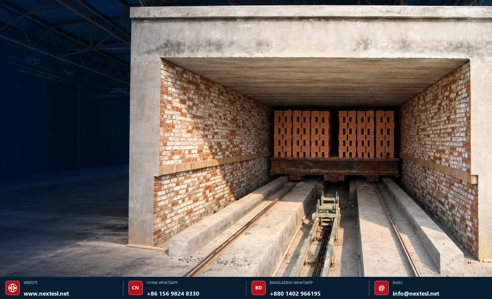
Editorial and engineering disclaimer: This article is educational and does not replace a site-specific design, hazard analysis, emissions review, OEM approval or commissioning procedure. Indicative savings are screening values only. The cover photograph is a real tunnel-kiln project image from the Next Engineering Solutions Ltd. website gallery; supporting visuals were created for this article.
Plan Your Tunnel Kiln & Tunnel Dryer Project with NES
Turn your production target, raw-material data and site constraints into a coordinated automatic clay-brick plant concept.
Next Engineering Solutions Ltd supports capacity selection, process and plant-layout planning, machinery configuration, tunnel kiln and dryer engineering, automation definition, installation guidance, commissioning coordination, operator training and after-sales support.