
Modern Tunnel Dryer Design: Reduce Drying Time, Cracks and Fuel Use
Published by Next Engineering Solutions Ltd. – Engineering Content Team · Last technically reviewed: 27 September 2026
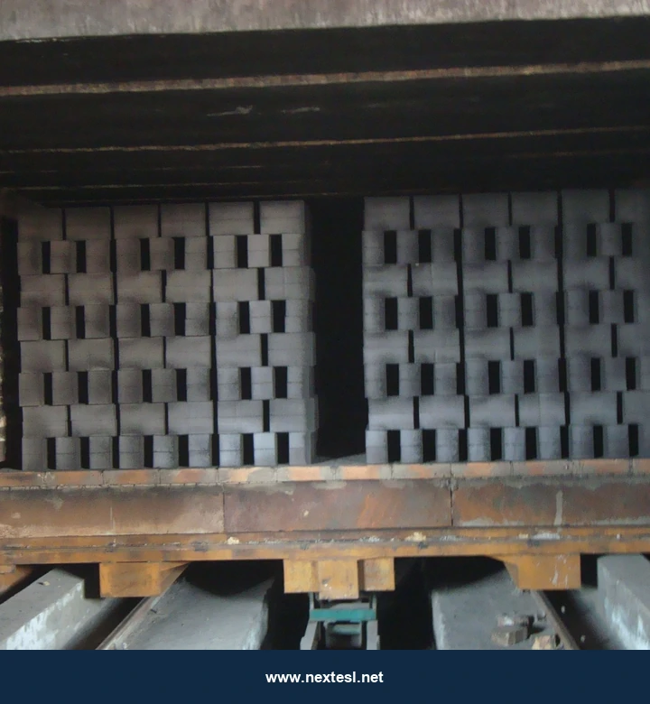
Drying is a capacity and quality constraint in many automatic clay-brick plants. A kiln cannot compensate for a green brick that arrives with a wet core, a crack or uneven shrinkage. A modern tunnel dryer combines a product-specific drying curve with zoned air control and useful heat recovery, then measures the result in saleable bricks per day.
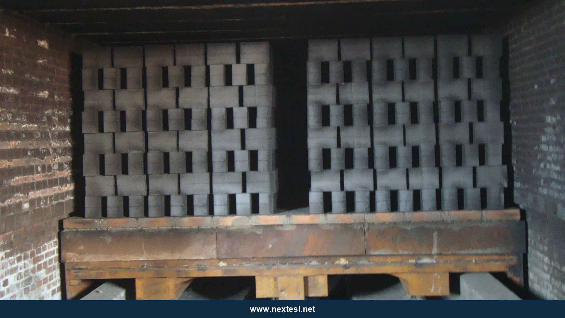
Photo note: In brickmaking, green means unfired—not green-coloured. The real plant photographs in this article show ash-grey green bricks before firing. Red fired bricks are not shown as dryer feed.
Quick answer
To reduce tunnel-dryer time, cracks and fuel use, protect green bricks during the shrinkage stage with controlled humidity and uniform, gentle airflow. Increase heat and moisture extraction after the clay reaches its tested critical moisture point. Balance air through the setting, seal leaks, recover stable kiln-cooling heat and control the dryer using product-moisture and energy measurements.
Key takeaways
- Test the clay's drying sensitivity before setting the tunnel profile.
- Control humidity, air temperature and air movement together.
- Fix blocked flow paths and air leaks before increasing fan speed.
- Measure water removed and saleable output alongside fuel and power.
- Size heat recovery from a plant heat balance, with kiln stability protected.
Contents
Why do green bricks crack during drying?
Drying removes water from the surface while moisture migrates outward from the core. If the surface dries and shrinks much faster than the interior, tensile stress can open surface or corner cracks. Differences between the top, bottom, centre and edge of a car add another source of uneven shrinkage. Excessively wet cores can also cause trouble during subsequent firing.
The Brick Development Association's process guide identifies temperature, humidity and air movement as the main controls of drying rate. It describes a tunnel profile that is cooler at entry and hotter and drier toward exit. Those figures are examples of practice, not a recipe for every clay.
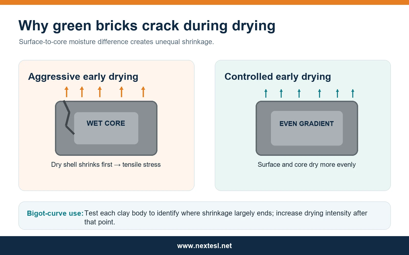
The practical target is the fastest safe removal rate. A shorter cycle has little value if more bricks are rejected or if the kiln receives a wider spread of residual moisture.
What is critical moisture and how is it tested?
The critical moisture point is the stage at which most drying shrinkage has ended for a particular body and geometry. A Bigot curve plots specimen shrinkage against moisture loss during drying. It helps reveal how long the early, crack-sensitive stage lasts. Laboratory brick tests have used Bigot curves to identify critical moisture and select a faster later-stage schedule. See the Marmara University tunnel-dryer study.
For each major product family, test representative bricks made with the plant's normal clay blend and forming conditions. Record starting moisture on a stated wet or dry basis, weight loss, linear shrinkage, visible damage and final strength. Repeat after meaningful changes to clay source, additives, perforation, wall thickness or extrusion conditions. Do not transfer a critical moisture value from another factory without testing.
How should a tunnel dryer be zoned?
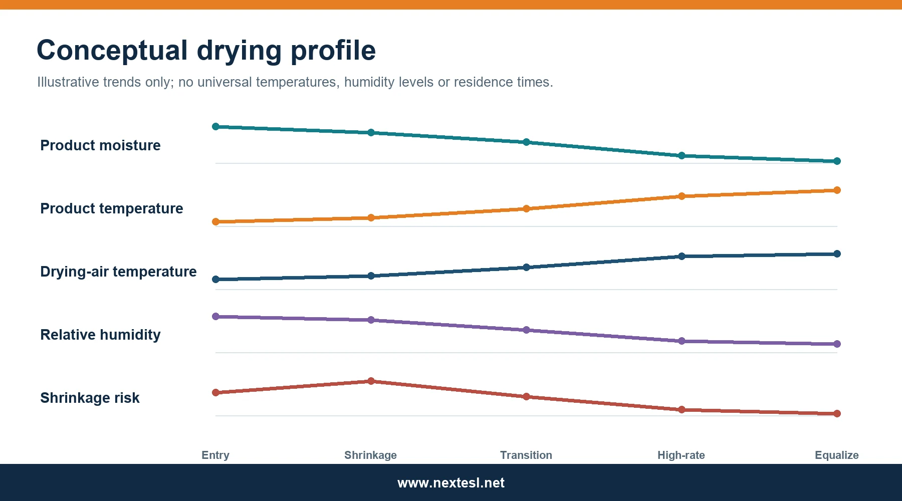
Zone names describe their purpose; the actual length, temperature and residence time require product trials. One useful design approach is shown below.
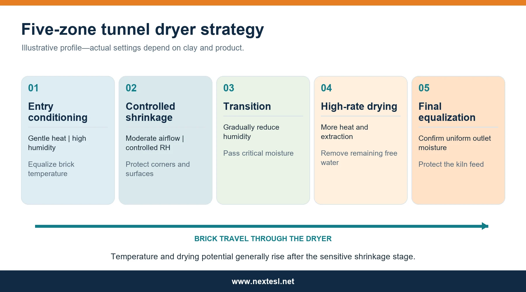
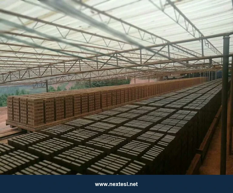
Swipe horizontally to view all columns →
| Dryer zone | Main purpose | Temperature approach | Humidity approach | Airflow approach | Main quality risk |
|---|---|---|---|---|---|
| Entry conditioning | Warm the green brick evenly | Gentle initial rise | Relatively humid, stable | Distributed, low-impact flow | Surface shock or condensation |
| Controlled shrinkage | Remove water without large gradients | Gradual rise | Control drying potential | Strong mixing without harsh jets | Corner and surface cracking |
| Transition | Pass the tested critical point | Increase as product permits | Reduce gradually | Improve through-pack exchange | Uneven shrinkage between car levels |
| High-rate drying | Remove remaining moisture efficiently | Higher useful heat | Lower than early zones | Higher, well-distributed exchange | Wet cores in sheltered packs |
| Final equalization | Narrow outlet-moisture spread | Match outlet specification | Avoid rewetting or over-drying | Even flow through all positions | Variable kiln feed moisture |
High internal recirculation can improve air uniformity while exhaust and fresh-air dampers set the moisture-removal rate. Each zone should have enough independent control to hold its profile when kiln heat supply, weather or throughput changes. The product's path through the dryer matters more than a single average tunnel temperature.
How should humidity, dew point and airflow be controlled?
Relative humidity (RH) describes how close the air is to saturation at its present temperature. Humidity ratio describes the mass of water vapour per mass of dry air, while dew point indicates when condensation will start. Tracking temperature and RH together lets the control system estimate the other two measures.
An exhaust stream should carry useful moisture, but a cold wall or duct surface below its dew point can condense water. Use insulated ducts, controlled exhaust and a measured condensation margin. Ambient air varies by season; a fixed fresh-air opening can give very different drying behaviour on a humid day and a dry day.
Air must pass through the brick setting, not mainly around it. Check supply and return plenums, fan position, nozzle direction, internal baffles, top and bottom car levels, wall gaps and rail-space leakage. Survey air velocity and temperature across a loaded car. If one location stays wet while another cracks, map both locations before increasing total fan speed. Industrial tunnel-dryer modelling has found uneven drying between brick layers, supporting the need to measure local conditions rather than rely only on tunnel averages. Applied Thermal Engineering study.
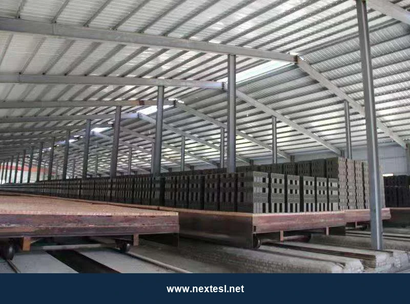
Variable-frequency drives allow circulation and exhaust fans to follow the required duty. Lower speed can save electrical power where airflow is excessive, but the final setting must still meet uniformity and moisture targets.
How do setting and pressure affect uniformity?
The setting pattern is part of the dryer design. Close-packed stacks, blocked perforations or misaligned channels restrict flow through the product. Very open bypass routes let air avoid the bricks. Compare centre, side, top and bottom moisture after the same residence time; revise pack spacing and plenum balance based on those results.
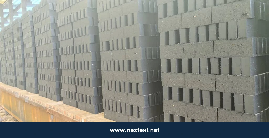
Measure static pressure at the supply, return, car and tunnel boundaries. Repair door seals and car gaps. Leakage changes both the heat balance and the local humidity, especially near the entrance. A plant may gain more from sealing and rebalancing than from a larger burner or fan.
Where should recovered heat come from?
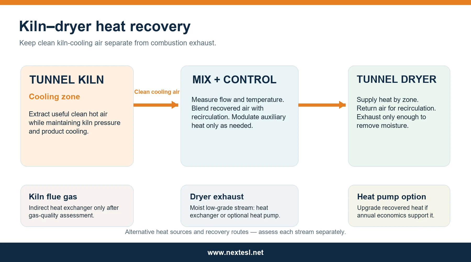
The first heat source to assess is usually clean air from the tunnel kiln's cooling zone. The Brick Development Association describes cooling-zone heat being fed to brick dryers. Extraction must be controlled so kiln pressure, brick cooling and firing remain stable.
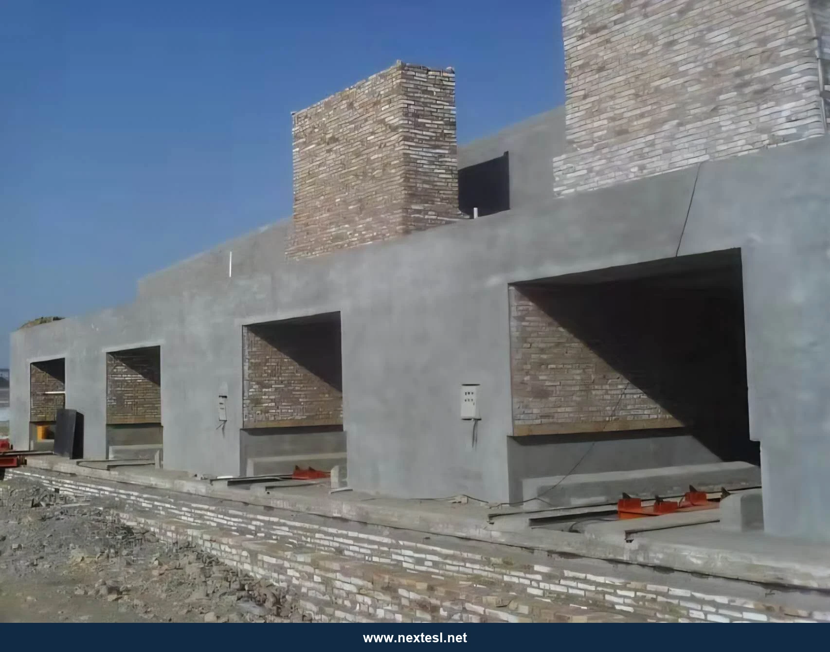
Kiln flue gas and moist dryer exhaust are separate streams with different risks. Flue-gas recovery needs a gas-quality, corrosion, fouling and dew-point assessment. Dryer exhaust may support air-to-air exchange, condensation or heat-pump recovery. The European Commission’s Ceramic Manufacturing Industry BREF page hosts the April 2026 final draft; it is a useful current technical reference but should not be described as adopted BAT conclusions.
Swipe horizontally to view all columns →
| Heat source or option | Temperature/value level | Advantages | Limitations | Best application | Relative investment |
|---|---|---|---|---|---|
| Clean kiln-cooling air | Usually high-value direct heat | Direct dryer supply; established integration | Kiln pressure and cooling must remain stable | Continuous kiln and dryer with matched schedules | Low–medium |
| Kiln flue-gas exchanger | Depends on exhaust conditions | Recovers heat otherwise discharged | Corrosion, fouling and pressure drop | Verified cleanable indirect circuit | Medium–high |
| Dryer-exhaust sensible exchange | Lower-grade heat | Preheats fresh air | Small temperature difference; condensation risk | Steady exhaust and nearby air demand | Medium |
| Condensing recovery | Low-grade sensible plus latent heat | Captures some water-vapour energy | Condensate treatment and exchanger maintenance | Wet exhaust with suitable heat sink | Medium–high |
| High-temperature heat pump | Upgrades low-grade heat | Can displace burner duty | Power price, temperature lift and capital cost | High annual operating hours | High |
| Thermal-energy storage | Time-shifts usable heat | Buffers supply and demand changes | Storage size and heat losses | Variable kiln or dryer duty | Medium–high |
These investment levels are screening judgments, not quotations. A heat balance and local prices are needed before selection.
What does a brick-drying heat-pump case study show?
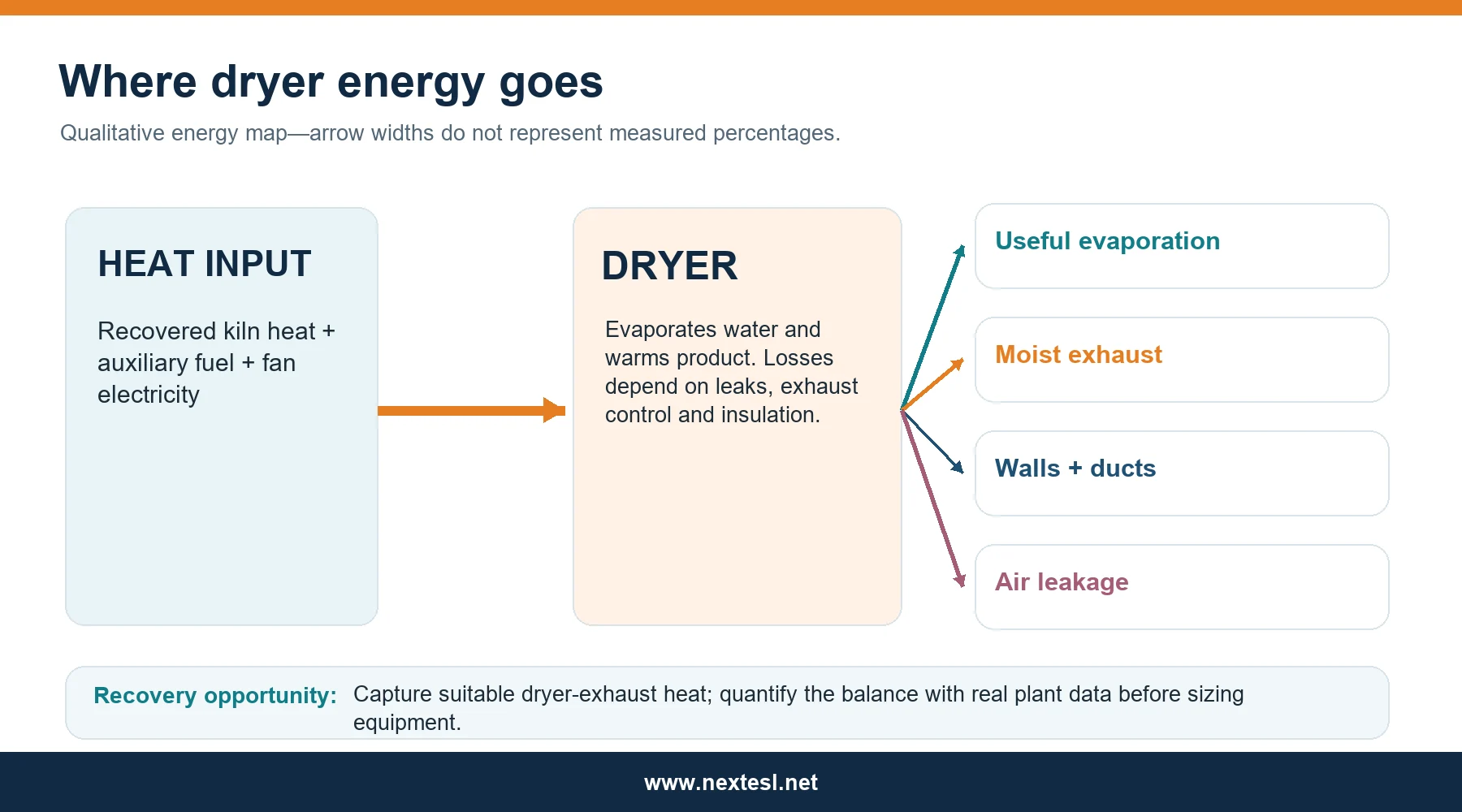
At Wienerberger's Uttendorf plant in Austria, an industrial heat-pump demonstrator was integrated with a tunnel dryer and supplied heat at up to 160°C. The IEA Heat Pumping Technologies case study reports more than 4,000 operating hours and a coefficient of performance from 5.0 at a lower temperature lift to 2.2 at a higher lift. Its reported energy and carbon savings apply to that installation. Plants should evaluate source temperature, electricity cost, annual hours, grid capacity and existing kiln heat before projecting their own result. The IEA HPT integration report sets out brick-drying integration concepts.
Which controls and new technologies are worth evaluating?
A dependable base system uses calibrated temperature and humidity sensors, pressure taps, fan and damper position feedback, fuel and power meters, and routine inlet and outlet moisture samples. Measure several heights and sides in important zones. A PLC and SCADA system should record trends, alarms and recipe changes by product and shift.
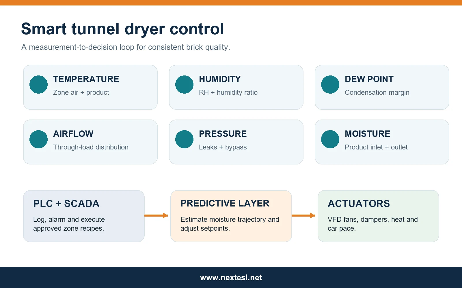
For moisture, regularly weighed test bricks remain valuable. Inline microwave or near-infrared instruments may add faster feedback, but they need calibration against oven-dry samples and checks for surface-to-core differences. CFD can be useful when redesigning ducts or car settings; it should be validated against measurements on a loaded dryer.
Model-predictive control and digital twins can estimate how a proposed fan, damper or heat change will affect later zones. A 2023 peer-reviewed roof-tile tunnel-dryer study optimized the shrinkage stage and reported a 1.5% fuel economy in its steady-state case while maintaining quality. That is evidence of a method, not a guaranteed saving for a brick plant. Apply advanced control only after sensors, seals, dampers and product recipes are dependable.
Which KPIs show whether the dryer is improving?
Compare results for the same product and inlet-moisture range. Report both thermal and electrical energy. Specify whether product mass is green, dried or fired when calculating per-tonne values.
Swipe horizontally to view all columns →
| KPI | Why it matters | Practical measurement |
|---|---|---|
| Residence time | Indicates capacity | Car interval × cars in tunnel |
| Inlet and outlet moisture | Confirms water duty | Oven-dry samples on a stated moisture basis |
| Outlet-moisture variation | Exposes nonuniform drying | Samples by car height, side and core |
| Drying rejection rate | Measures cracks and warpage | Rejected units ÷ dryer output |
| Kiln rejection linked to drying | Captures downstream damage | Defect coding by cause |
| Thermal MJ per tonne | Tracks fuel and recovered heat use | Metered heat ÷ stated product mass |
| Thermal MJ per kg water evaporated | Normalizes changing inlet moisture | Heat input ÷ measured water removed |
| Fan kWh per tonne | Tracks electrical duty | Fan submeter ÷ output mass |
| Waste-heat contribution | Tests recovery performance | Metered recovered heat ÷ total heat supplied |
| Exhaust temperature, RH and dew point | Shows moisture removal and condensation margin | Duct instruments |
| Top-to-bottom temperature spread | Shows distribution | Multi-point zone survey |
| Saleable tonnes per day | Combines capacity and quality | Accepted fired output |
Practical dryer troubleshooting
Swipe horizontally to view all columns →
| Observed problem | Probable causes | Measurements to check | Practical corrective action |
|---|---|---|---|
| Surface cracks | Early air too dry or too hot | Entry RH, surface temperature, crack location | Soften early drying; remove direct jets |
| Corner cracks | Local airflow concentration | Nozzle direction and corner velocity | Rebalance supply and protect exposed corners |
| Internal cracks | Surface-to-core gradient | Core and surface moisture | Extend controlled-shrinkage stage |
| Warped bricks | Uneven support or drying | Car-level temperature, setting geometry | Correct support and cross-flow balance |
| Wet cores | Sheltered packs or short residence | Core moisture by location | Open flow channels; confirm later-zone duty |
| Condensation | Surface below air dew point | Dew point and duct-wall temperature | Insulate and adjust exhaust or mixing |
| Uneven top-to-bottom drying | Plenum or return imbalance | Multi-height air and moisture map | Rebalance dampers and recirculation |
| High fuel use | Leaks, hot exhaust or excess fresh air | Heat balance, damper positions | Seal, tune exhaust and recover heat |
| High exhaust temperature | Excess heat leaving | Exhaust flow, temperature and RH | Recheck air rate and recovery opportunity |
| High fan electricity | Excess speed or pressure drop | Fan kW and system pressure | Clean ducts; optimize speed and setting |
| Seasonal inconsistency | Fixed recipe despite ambient changes | Outdoor temperature and humidity | Add ambient-compensated recipes |
What should a plant upgrade first?
- Establish a baseline. Record moisture, cracks, saleable output, fuel, fan power, airflow and zone conditions for representative products and weather.
- Characterize the clay. Use drying and shrinkage tests to identify the sensitive stage for each major body.
- Fix physical defects. Repair leaks, insulation, failed dampers, blocked plenums and poor car seals.
- Balance setting and airflow. Survey loaded cars and remove bypass paths before increasing total fan flow.
- Tune zone recipes. Protect early shrinkage, then accelerate drying where test bricks show it is safe.
- Optimize stable kiln heat recovery. Meter the heat delivered and protect kiln operation.
- Evaluate advanced recovery and control. Compare full-year fuel, power, maintenance and capital cost before adding heat pumps or predictive control.
For a new dryer supplier specification, request a guarantee based on identified products, clay and inlet moisture; required outlet moisture and variation; acceptable drying rejection; production range; fuel and fan energy boundaries; seasonal ambient cases; airflow uniformity; sensor locations; heat-recovery control; maintenance access; and an acceptance test on loaded cars. Ask suppliers to state the measurement method and guarantee conditions in writing.
Conclusion
The strongest design choice is a product-specific drying profile supported by uniform through-pack airflow, controlled exhaust, measured kiln heat recovery and reliable moisture data. Evaluate every change by the same combined result: more saleable brick at the required kiln-feed moisture with less fuel and electricity per unit of water removed.
Why Next Engineering Solutions Ltd.?
Next Engineering Solutions Ltd. supports automatic clay-brick plant projects from feasibility and capacity planning through clay and product review, plant layout, machinery selection and supply, tunnel-kiln and tunnel-dryer integration, installation, commissioning and operator training. NES can also coordinate waste-heat and automation planning, spare parts and after-sales support. The dryer should be specified as part of the complete production line, with throughput and kiln-feed quality matched to the kiln.
Planning a new tunnel dryer or improving an existing one? Share your product sizes, clay data, target capacity, fuel, kiln type and current drying problems.
China WhatsApp: +86 156 9824 8330 · Email: info@nextesl.net · Website: www.nextesl.net
Frequently asked questions
Can a tunnel dryer run faster without increasing cracks?
Often, yes, if the current bottleneck is airflow imbalance, leakage or an overly conservative later stage. First test the clay’s critical moisture point and correct nonuniform flow. Then shorten the cycle in controlled trials while tracking cracks and outlet core moisture.
Why is high humidity useful near the dryer entrance?
It reduces early drying potential while green bricks warm and begin to shrink. The correct humidity depends on the clay, brick geometry and temperature; avoid settings that cause condensation.
Should the plant increase fan speed to dry wet cores?
Map moisture and air paths first. More total airflow may bypass dense packs or intensify cracks at exposed faces. Correct setting, plenums and leakage before raising fan speed.
What is the best heat source for a brick tunnel dryer?
Clean kiln-cooling air is often the first source to evaluate when a tunnel kiln and dryer run together. The recoverable duty must be limited by kiln pressure, cooling and product requirements.
How should dryer energy efficiency be compared?
Record thermal energy per kilogram of water removed, fan electricity per tonne, saleable output and rejection rate for the same product and inlet-moisture range. State the heat and mass boundaries used.
Are industrial heat pumps practical for brick dryers?
They can be. An Austrian brick plant has demonstrated high-temperature heat-pump integration, but each project needs a site-specific analysis of heat source, temperature lift, operating hours, electricity cost and capital cost.
What should a buyer require from a dryer supplier?
Specify product and clay conditions, capacity, outlet-moisture spread, allowable rejects, energy measurement boundaries, seasonal ambient cases, heat-recovery control, instrumentation and a loaded-car acceptance test.
Technical references
- Brick Development Association, The UK Clay Brickmaking Process (2023).
- European Commission JRC, Ceramic Manufacturing Industry BREF page, including April 2026 final draft. The draft has not been adopted as final BAT conclusions.
- IEA Heat Pumping Technologies, High-Temperature Heat Pumps: Integration Concepts (2024).
- IEA Heat Pumping Technologies, Wienerberger Uttendorf brick-drying case study.
- Arvanitidis et al., Optimal Tunnel Dryer Operating Strategies for the Production of Ceramic Roof Tiles, Industrial & Engineering Chemistry Research (2023).
- Almeida et al., Heat and Mass Transport in an Industrial Tunnel Dryer, Applied Thermal Engineering (2013).
- Özen, Experimental Investigation of Convective Drying of Green Bricks in a Laboratory Scale Tunnel Dryer, Marmara University (2014).