
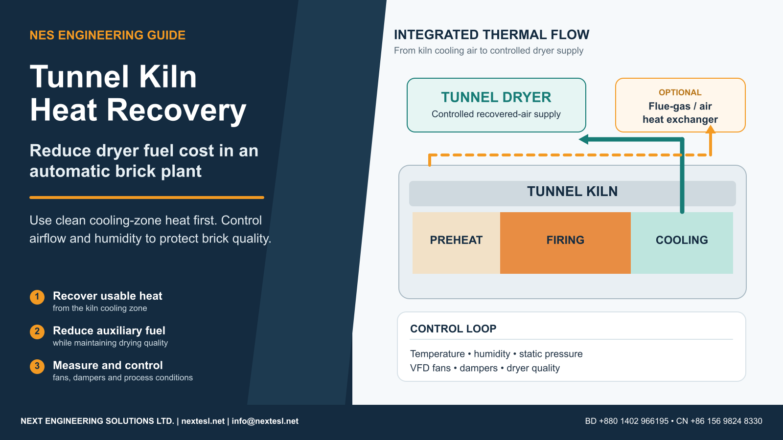
In an automatic clay brick plant, the tunnel kiln and tunnel dryer should be designed as one thermal system. The kiln releases useful heat—especially while fired bricks are being cooled—while the dryer continuously needs thermal energy to evaporate water from green bricks. A properly engineered heat-recovery system connects these two duties so that heat already paid for in the firing process is reused before additional dryer fuel is burned.
Article contents
Why This Matters for Modern Brick Plants
European ceramic-industry best-available-technique guidance has long treated kiln heat recovery as a core energy-efficiency measure. The European Commission’s Joint Research Centre (JRC) currently hosts the April 2026 Final Draft of the Ceramic Manufacturing Industry BREF, covering bricks and roof tiles as well as other fired ceramics. In the revised technical text, recovery of excess heat from kilns includes cooling-zone heat, flue gas and other waste-heat sources; it also stresses that plant layout, short heat-transfer distances and pipe insulation strongly affect the value of low-temperature recovered heat.
The same guidance notes an important limitation: flue-gas heat recovery can face corrosion problems and may be unattractive when exhaust temperature is too low. This is exactly why an engineering study must distinguish clean cooling air from combustion exhaust gas rather than treating every hot stream as interchangeable.
1. Start With the Dryer Load — Not the Recovery Fan
The first question is not “How much hot air can the kiln provide?” It is “How much moisture must the dryer remove, and at what rate?” Every kilogram of water evaporated carries a substantial latent-heat requirement. Depending on temperature, the phase-change energy alone is roughly in the range of 2.3–2.5 MJ/kg of water, before sensible heating of bricks and air, dryer-shell loss, leakage and exhaust loss are included.
This is why two plants producing the same number of bricks per day can have very different dryer energy demand. Brick mass, extrusion moisture, residual moisture, clay mineralogy, product geometry, setting pattern, ambient humidity and drying time all matter.
Useful moisture-balance formula
If moisture is reported on a wet basis, convert it before estimating evaporation:
where X = moisture fraction on wet basis.
Water evaporated = Water at dryer inlet − Water at dryer outlet
Example: if 100 tonnes/day of dry solids enter the dryer at 20% wet-basis moisture and leave at 2% wet-basis moisture, the dryer must remove about 23 tonnes of water per day. That water load—not brick count by itself—is what the heat-recovery system must serve.
| Input | Why It Matters | Recommended Measurement |
|---|---|---|
| Green-brick moisture | Determines the water that must be evaporated. | At extruder/cutter and representative dryer entry. |
| Dry product mass | Converts brick count into a true material balance. | kg/brick × saleable bricks/day or tonnes/day. |
| Dryer exhaust T & RH | Shows how effectively the air is carrying moisture away. | Temperature, RH/dew point and exhaust airflow. |
| Kiln cooling air | Usually the first-choice recovered heat stream. | Temperature, volume/mass flow and static pressure. |
| Auxiliary dryer fuel | Creates the baseline for verified savings. | Fuel flow, calorific value, hours and burner efficiency. |
| Saleable output | A low fuel number is meaningless if rejects rise. | Good fired tonnes/day + reject categories. |
2. Where Recoverable Heat Comes From
A. Cooling-zone hot air — normally the first priority
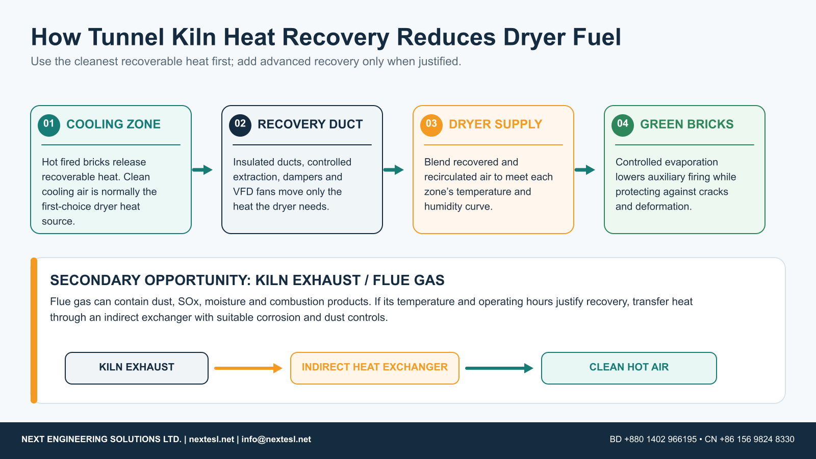
After firing, the brick body and kiln furniture still contain large quantities of sensible heat. Ambient air introduced for controlled cooling absorbs part of that energy. Published tunnel-kiln research and the JRC ceramic-industry guidance both identify the cooling zone as a major heat-recovery location.
Cooling air is attractive because it is normally much cleaner than combustion exhaust. Depending on kiln design, a controlled portion can be extracted, transported through insulated ducting and blended with dryer supply or recirculation air.
B. Kiln exhaust / flue gas — useful, but not automatically “free heat”
Flue gas can still carry meaningful thermal energy. However, coal, pet coke, biomass or sulphur-bearing clay can create particulate, SOx and condensable species. An exchanger therefore adds pressure drop, cleaning needs and potential corrosion risk. Cooling exhaust below its safe dew-point margin can create acidic condensate on metal surfaces.
The JRC ceramic-industry BREF text specifically warns that kiln flue-gas heat exchangers may be limited by acid-gas corrosion and insufficient exhaust temperature. This makes material selection, bypass control, fouling allowance and maintenance access essential parts of the design.
C. Dryer exhaust — low-grade heat with growing future value
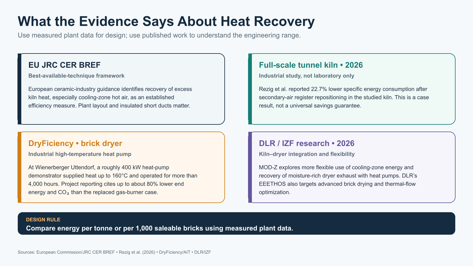
Dryer exhaust is often lower-temperature and moisture-rich, so conventional direct recovery may be difficult. But heat pumps can raise this heat to a useful temperature. The EU-funded DryFiciency project demonstrated a high-temperature heat pump at Wienerberger’s Uttendorf brick plant in Austria. The demonstrator was around 400 kW heating capacity, supplied heat up to 160°C, and operated for more than 4,000 hours. Project reporting states end-energy savings of up to about 80% and CO₂ reductions of about 80% versus the replaced gas-burner case.
Those figures are important evidence that high-temperature heat pumps can work in industrial brick drying, but they are not directly transferable to a Bangladesh or India coal-fired plant. Electricity price, grid reliability, temperature lift, annual load factor and existing waste-heat quality determine whether the economics are attractive.
3. What Recent Research Says: Airflow Control Can Be as Important as Hardware
A major 2026 development is a full-scale industrial study published in Heat and Mass Transfer. Rezig and co-authors investigated secondary-air register positioning in an operating tunnel kiln under real production conditions. The intervention did not require a new kiln or a major heat exchanger; it changed how heat and gas residence time were distributed in the preheating zone.
In the studied kiln, register repositioning reduced specific energy consumption by 22.7%, improved direct thermal efficiency by 4.16 percentage points, reduced gas use by a reported 631.37 kW equivalent, and lowered operating cost from 19.15 to 14.80 DT/ton. Unrecovered thermal power at the chimney fell from about 1,500.61 to 1,287.39 kW. The authors also report that the gains persisted under a production regime about 23.6% higher, without measurable loss in brick quality.
Earlier cooling-zone research supports the same principle. Model-based work by Kaya, Küçükada and Mançuhan showed that suction and blowing configuration can be optimized to improve cooling-zone heat recovery while controlling pressure drop. A 2017 study by Soussi and co-authors examined the recovered-air mass flow between cooling and firing zones; a 2026 review of tunnel-kiln technology summarizes fuel reduction in the studied system at about 4.6% after optimization. The important point is not the exact percentage—it is that there is an optimum airflow, not simply “the more recovered air, the better.”
Rezig et al. (2026), Heat and Mass Transfer: DOI 10.1007/s00231-026-03748-8.
Refaey & Almohammadi (2026), Energies review: Advances in Tunnel Kiln Technology for Sustainable Ceramic Manufacturing.
4. A Practical Heat-Recovery Hierarchy
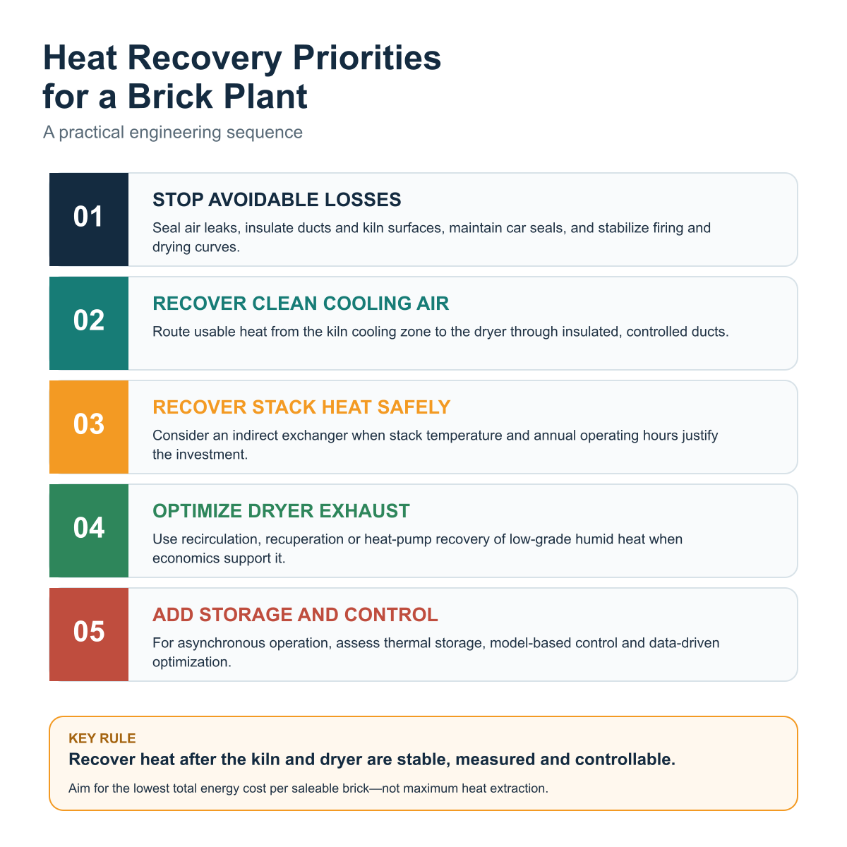
- Stop avoidable losses. Repair false-air leakage, kiln-car sealing, hot-duct leakage and damaged insulation before buying new recovery equipment.
- Stabilise kiln and dryer control. Heat cannot be recovered efficiently from an unstable process.
- Recover clean cooling-zone air. This is usually the simplest high-value heat source for brick drying.
- Optimise dryer recirculation and exhaust. Hot exhaust with poor moisture loading is an efficiency warning.
- Evaluate flue-gas heat recovery. Use an indirect exchanger when temperature, annual hours, fouling and corrosion economics justify it.
- Evaluate heat pumps / thermal storage. These become useful when kiln and dryer schedules do not match or low-grade exhaust heat remains valuable.
5. Kiln–Dryer Coupling: Why Timing Matters
Conventional brickworks often depend on simultaneous kiln cooling and dryer heat demand. This works well when both processes operate continuously and at compatible load. It becomes less efficient when the kiln runs while the dryer is stopped, when production shifts are different, or when dryer demand changes sharply with product or weather.
This problem is receiving new research attention. The 2026 MOD-Z project led by the Institute for Brick Research Essen (IZF) and the DLR Institute of Low-Carbon Industrial Processes is investigating the decoupling of tunnel kilns and dryers. The project aims to use cooling-zone energy more efficiently while examining heat pumps that exploit moisture-rich dryer exhaust.
DLR’s current EEETHOS programme goes further, developing advanced high-temperature heat pumps, superheated-steam drying for brick production and digital-twin-based thermal optimization. These are emerging technologies, not yet the default solution for South Asian plants, but they show the likely direction of future high-efficiency brick manufacturing.
6. How Much Heat Is Actually Recoverable?
For a clean hot-air stream, a first-pass heat calculation can be made from air mass flow and temperature difference:
Q̇ = thermal power, kW
ṁ = air mass flow, kg/s
cp = specific heat capacity of air, kJ/kg·K
T = temperature, °C or K difference
But this is only the available sensible heat. The usable amount will be lower because of duct loss, minimum required kiln cooling, temperature limits in the dryer, control margin and periods when dryer demand is lower than kiln heat availability.
For fan power, the electrical penalty should also be checked:
A heat-recovery design is economically better only when the value of displaced fuel/heat is greater than the added fan electricity, maintenance and capital cost.
7. Control Philosophy: Kiln Stability Must Have Priority
The heat-recovery control system should be designed so that a dryer problem cannot pull the kiln out of its safe operating window. A practical control philosophy normally uses the kiln as the protected process and the dryer as the heat-demand process.
| Instrument / Control | Primary Function | Design Note |
|---|---|---|
| Recovery fan + VFD | Matches recovered-air flow to demand. | Control by temperature/pressure limits, not manual Hz alone. |
| Motorized dampers | Blend fresh, recovered and recirculated air. | Define fail-safe positions on power/PLC failure. |
| Static-pressure transmitters | Protect kiln draft and monitor duct resistance. | Use several points; one chimney reading is not enough. |
| Temperature sensors | Measure source, duct and dryer-zone temperature. | Needed for heat balance and over-temperature protection. |
| RH / dew-point measurement | Indicates moisture-carrying capacity of dryer air. | Select sensors suitable for dusty, hot environments. |
| PLC / SCADA historian | Links heat flow, fan speed, fuel, output and quality. | Essential for verifying actual ROI after commissioning. |
8. Dryer Quality Comes Before Maximum Temperature
Drying is a heat-and-mass-transfer process, not just heating. In the early stage, if the surface of a green brick loses water much faster than moisture can migrate from the core, differential shrinkage creates cracks or deformation. High temperature with low humidity is therefore not automatically “faster and better.”
The dryer should be tuned around a controlled curve of temperature, humidity and air velocity. The optimum curve depends on clay plasticity, particle size, pore structure, forming moisture, product thickness, perforation, stacking geometry and drying sensitivity.
NES’s related technical guide on green brick drying problems and tunnel dryer solutions discusses cracking, deformation, wet cores and airflow imbalance in more detail.
9. Plant Layout Has a Direct Energy Cost
Heat-recovery systems are often added after the kiln, dryer and building layout are already fixed. That can create long duct routes, extra bends, oversized fans and higher heat loss. The JRC ceramic BREF specifically highlights the importance of keeping low-temperature heat-transfer distances short and insulating piping or ducts appropriately.
For a new plant, the kiln, dryer and heat-recovery corridor should be planned together. Allow space for:
- short insulated hot-air ducts;
- fan and damper maintenance platforms;
- inspection and cleaning doors;
- future heat exchanger installation;
- instrument tapping points;
- condensate drainage if flue-gas cooling is considered;
- bypass ducts / emergency discharge;
- safe access without stopping the main production line.
NES’s 50K–240K/day tunnel kiln and tunnel dryer guide provides the broader plant-flow and capacity context for integrated automatic brick plants.
10. How to Calculate Fuel Savings and ROI Properly
Savings should be calculated from a defined baseline and measurement boundary. A statement such as “heat recovery saves 20% fuel” is technically incomplete unless it specifies whether that means dryer auxiliary fuel, kiln fuel, total thermal energy, total energy cost or CO₂.
1. Measure available heat and usable fraction.
2. Calculate annual useful recovered energy.
3. Convert that energy to displaced fuel using the existing heater efficiency.
4. Subtract additional electricity, cleaning and maintenance cost.
5. Compare net annual saving with installed CAPEX.
6. Verify the result again after commissioning using logged plant data.
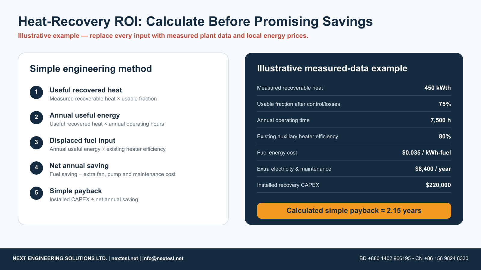
Fuel-displacement formula
For coal-fired systems, use the actual tested calorific value, not only supplier invoice tonnage. A lower-grade coal can make “tonnes per 100,000 bricks” appear worse even when thermal efficiency is unchanged. This is why MJ/kg fired product is a better technical KPI.
11. The Best KPIs for an Automatic Brick Plant
- Total thermal energy: MJ/kg or GJ/tonne of saleable fired product.
- Auxiliary dryer fuel: MJ/tonne or fuel kg/1,000 bricks corrected for product mass.
- Electricity: kWh/1,000 saleable bricks or kWh/tonne.
- Water evaporated: tonnes/day and kg water/kg dry product.
- Dryer exhaust condition: temperature, RH/dew point and airflow.
- Recovered heat: estimated/measured kWth and annual operating hours.
- Rejects: drying crack %, deformation %, under/over-fire %, handling loss %.
- Commercial KPI: total energy cost per 1,000 saleable bricks.
12. Bangladesh & South Asia: Practical Relevance
Bangladesh has a long history of development-finance efforts aimed at replacing inefficient brick kilns with cleaner technologies. The Asian Development Bank’s Brick Kiln Efficiency Improvement Project classified tunnel kilns among the more energy-efficient and lower-polluting kiln options considered for modernization and provided financing support for advanced kiln projects.
That institutional history does not mean every tunnel kiln is automatically efficient. Fuel performance still depends on clay, setting density, refractory/insulation, leakage, kiln-car thermal mass, fan control, fuel preparation, firing curve, dryer integration and operator discipline. The modern design opportunity is to combine continuous firing with measurable heat recovery and controls rather than relying only on the kiln name.
13. New Plant vs Retrofit — Different Engineering Strategy
| Project Type | Best Opportunity | Main Risk |
|---|---|---|
| New tunnel kiln + dryer | Integrate heat balance, layout, short ducting, fans and controls before civil construction. | Buying machinery before the clay/dryer load is defined. |
| Existing kiln, high dryer fuel | Measure unused cooling heat, leakage and dryer exhaust first. | Expensive duct routing and insufficient measurement points. |
| Existing recovery system | Optimize dampers, fan speed, insulation, pressure and recirculation before replacing equipment. | Assuming the fan is the problem when the real issue is airflow distribution. |
14. Common Heat-Recovery Mistakes
- Designing from temperature only. A 180°C stream with very low mass flow may contain less useful energy than a larger 110°C stream.
- Ignoring dryer humidity. Air can be hot but have little remaining capacity to absorb water.
- Over-extracting cooling air. This can disrupt kiln cooling or upstream thermal balance.
- Using one fixed fan speed. Output, product, season and moisture load change.
- Failing to measure static pressure. Flow problems are often pressure problems.
- Sending dirty flue gas directly to the dryer without review. Product contamination, corrosion and environmental issues can result.
- Long uninsulated ducts. Low-grade heat loses value quickly.
- Ignoring fan electricity. A recovery project should reduce total energy cost, not only fuel.
- Quoting a universal savings percentage. Credible savings require a baseline heat and mass balance.
15. What a Professional Heat-Recovery Proposal Should Include
A serious quotation should contain more than the line item “waste heat recovery system.” For a new automatic tunnel kiln plant, request the following:
- design source temperature range and expected airflow/mass flow;
- heat balance showing available, recoverable and usable kW;
- recovery fan operating point, efficiency and VFD range;
- duct cross-section, length, major bends and insulation specification;
- pressure-loss calculation and damper/bypass arrangement;
- dryer supply-air temperature and humidity control philosophy;
- kiln pressure limits and interlock logic;
- temperature, RH/dew-point and pressure sensor schedule;
- PLC/SCADA trend logging;
- auxiliary burner/fuel system and turndown range;
- measurement boundary for any fuel-saving guarantee;
- commissioning test protocol and acceptance criteria;
- maintenance access, cleaning points and corrosion allowance where flue gas is involved.
16. Evidence Table — What Can Be Used in a Proposal?
| Evidence | What It Shows | How NES Should Use It |
|---|---|---|
| EU JRC CER BREF | Kiln cooling-zone heat recovery is an established energy-efficiency technique; layout and insulation matter. | Use as design-principle / best-practice support, not a savings guarantee. |
| Rezig et al., 2026 | Full-scale kiln showed large SEC improvement from airflow/register optimization. | Use to justify instrumentation and airflow optimization; label results case-specific. |
| Kaya / Soussi studies | Cooling-zone suction/blowing and recovered-air flow have an optimum. | Use to justify pressure-drop and flow calculations rather than simple fan sizing. |
| DryFiciency | High-temperature heat pump successfully demonstrated in industrial brick drying. | Present as advanced/future option; run local electricity/gas ROI before recommending. |
| MOD-Z / EEETHOS | Industry R&D is moving toward kiln-dryer decoupling, heat pumps and digital thermal optimization. | Use as technology-watch information, not proven commercial performance for every plant. |
| ADB Bangladesh | Modern kiln technologies were promoted as part of brick-sector efficiency modernization. | Use for Bangladesh investment context, not to claim a specific tunnel-kiln fuel rate. |
Conclusion
Tunnel kiln heat recovery is one of the most logical energy-efficiency opportunities in automatic clay brick manufacturing because the plant already produces recoverable high-temperature energy during firing and cooling. But the best results come from treating the kiln, dryer, airflow system, controls and plant layout as one integrated process.
For most new South Asian automatic brick plants, the practical priority is: stable kiln operation → controlled cooling-zone heat recovery → short insulated ducting → VFD-controlled airflow → dryer temperature/humidity control → measured KPI tracking. Only after those fundamentals are working well should the project move to more complex flue-gas exchangers, heat pumps, thermal storage or digital-twin optimization.
The strongest commercial promise is therefore not “our system saves X% fuel.” A technically credible promise is: the plant will be designed with a defined heat balance, measurable recovery system, controllable airflow, instrumented performance and an agreed commissioning method to verify actual savings.
Planning a Tunnel Kiln & Tunnel Dryer Project?
Next Engineering Solutions Ltd. (NES) provides feasibility support, plant layout, clay and capacity review, machinery selection, kiln and dryer engineering, heat-recovery planning, installation guidance, commissioning and after-sales technical support.
Website: www.nextesl.net
Email: info@nextesl.net
Bangladesh WhatsApp: +880 1402 966195
China WhatsApp: +86 156 9824 8330
Bangladesh Office: House 459, Road 8, Baridhara DOHS, Dhaka 1206, Bangladesh
China Office: Bai Ma Shan Office, Shi Zhong District, Jinan City, Shandong Province, China
Frequently Asked Questions
Can tunnel kiln cooling air be used directly in a tunnel dryer?
Often yes, if the air is sufficiently clean and its flow and temperature are controlled. The recovered air should be blended and distributed according to the dryer’s required temperature, humidity and airflow curve—not simply connected with a permanently open duct.
How much dryer fuel can heat recovery save?
There is no universal percentage. The saving depends on moisture load, existing auxiliary fuel use, kiln cooling heat, operating hours, duct loss, dryer efficiency and control quality. A measured heat balance is required before giving a credible project estimate.
Is cooling-zone heat better than kiln flue-gas heat?
Cooling-zone air is normally the easier first option because it is comparatively clean. Flue gas can contain dust and corrosive or condensable species, so it may require an indirect exchanger, cleaning and careful material selection.
Do VFD fans reduce energy use?
They can. VFDs allow airflow to follow actual heat and pressure demand instead of relying on constant-speed operation with heavy throttling. The real saving depends on the fan/system curve and control strategy.
Can heat pumps replace dryer burners?
In some industrial applications, yes. The DryFiciency demonstration showed high-temperature heat-pump operation in a brick tunnel dryer. Economic suitability for Bangladesh, India or other markets must be calculated from electricity cost, heat-source temperature, load factor and required supply temperature.
What data should a plant owner provide for a heat-recovery study?
Capacity, brick dimensions and mass, clay type, extrusion moisture, dryer-out moisture, kiln and dryer dimensions, firing temperature, fuel type and calorific value, current dryer fuel use, cooling-zone temperatures, stack temperature, fan data, operating schedule, reject rate and plant layout.
Technical References & Authentic Sources
- European Commission, Joint Research Centre (JRC). Best Available Techniques Reference Document for the Ceramic Manufacturing Industry (CER BREF). Official page currently hosts Final Draft, April 2026. Official source.
- Rezig, K., Gannouni, S., Ben Chihaoui, F. et al. (2026). “Enhancing energy efficiency in brick firing: Experimental study of convective heat transfer in the preheating zone of a tunnel kiln.” Heat and Mass Transfer, 62, 118. Springer / DOI.
- Refaey, H.A. & Almohammadi, B.A. (2026). “Advances in Tunnel Kiln Technology for Sustainable Ceramic Manufacturing: Heat Transfer, Energy Efficiency, and Digital Optimization.” Energies, 19(9), 2219. Open-access review.
- Kaya, S., Küçükada, K. & Mançuhan, E. (2008). “Model-based optimization of heat recovery in the cooling zone of a tunnel kiln.” Applied Thermal Engineering, 28(5–6), 633–641. DOI.
- Soussi, N., Kriaa, W., Mhiri, H. & Bournot, P. (2017). “Reduction of the energy consumption of a tunnel kiln by optimization of the recovered air mass flow from the cooling zone to the firing zone.” Applied Thermal Engineering, 124, 1382–1391. DOI.
- DryFiciency / AIT Austrian Institute of Technology. Industrial high-temperature heat-pump demonstration at Wienerberger brick production, Uttendorf, Austria. Project page.
- Institute for Brick Research Essen (IZF) + DLR Institute of Low-Carbon Industrial Processes. MOD-Z project, 2025–2027: kiln/dryer decoupling and heat-pump integration. Project description.
- DLR Institute of Low-Carbon Industrial Processes. EEETHOS project: high-temperature heat pumps, superheated steam drying for bricks and digital thermal optimization. DLR source.
- Asian Development Bank. Financing Brick Kiln Efficiency Improvement Project — Bangladesh. ADB project page.